ORIGINAL RESEARCH ARTICLE
Improving standard volar plate fixation in 3D-guided corrective osteotomy of the distal radius: evaluation of a shim instrument
Emilia Gryskaa,b#, Katleen Libberechta,b#, Charlotte Stor Swinkelsa,b,c, Peter Axelssona,b, Per Fredriksona,b and Anders Björkmana,b
aDepartment of Hand Surgery, Sahlgrenska University Hospital, Mölndal, Sweden; bInstitute of Clinical Sciences, Sahlgrenska Academy, University of Gothenburg, Gothenburg, Sweden; cDepartment of Medical Physics and Biomedical Engineering, Sahlgrenska University Hospital, Gothenburg, Sweden
ABSTRACT
Standard volar plates often do not fit the surface of the malunited distal radius after osteotomy, necessitating an offset angle for accurate volar tilt correction. The correction can be achieved if the plate is held at the correct angle when the distal screws are locked. With the advantage of 3D surgical planning and patient-specific instruments, we developed a shim instrument to assist the surgeon in securing the plate at the intended angle when locking the distal screws, and evaluated radiological results. Five female patients aged 63–74 with dorsally angulated extra-articular malunions underwent surgery using 3D-printed guides and the shim instrument. The plate position, drilling guide alignment, screw placements, and distal radius correction on postoperative CTs were compared with the surgical plans. Errors were measured using an anatomical coordinate system, and standard 2D radiographic measures were extracted. Preoperative dorsal tilt ranged from 16° to 35°, and postoperative volar tilt from 1° to 11°. 3D analysis revealed mean absolute correction errors of 6.1° in volar tilt, 1.6° in radial inclination, and 0.6 mm in ulnar variance. The volar tilt error due to the shim instrument, indicated by the mean angle error of the distal screws to the plate, was 2.1° but varied across the five patients. Settling of the distal radius, due to tension during and after reduction, further contributed to a mean loss of 3.5° in volar tilt. The shim instrument helped with securing plates at the intended angle; however, further correction improvements should consider the tension between the fragments of osteoporotic bone.
KEYWORDS: Virtual surgical planning; 3D printing; patientspecific instruments; distal radius; extra-articular; osteotomy.
Citation: Journal of Plastic Surgery and Hand Surgery 2024; 59: 46–52. DOI: https://doi.org/10.2340/jphs.v59.39839.
Copyright: © 2024 The Author(s). Published by MJS Publishing on behalf of Acta Chirurgica Scandinavica. This is an Open Access article distributed under the terms of the Creative Commons Attribution 4.0 International License (http://creativecommons.org/licenses/by/4.0/), allowing third parties to copy and redistribute the material in any medium or format and to remix, transform, and build upon the material, with the condition of proper attribution to the original work.
Received: 15 January 2024; Accepted: 25 April 2024; Published: 15 May 2024.
CONTACT Emilia Gryska emilia.gryska@gu.se Department of Hand Surgery, Sahlgrenska University Hospital, Mölndal, Sweden
#Authors contributed equally to this manuscript.
Supplemental data for this article can be accessed online at https://doi.org/10.2340/jphs.v59.39839
Competing interests and funding: The authors report there are no competing interests to declare.
Introduction
It has been shown that more accurate correction of malunion of the distal radius leads to better clinical results [1,2]. The correction that falls within 5° in volar tilt and 2 mm in ulnar variance from normal has been defined as clinically insignificant [3]. The use of three-dimensional (3D) virtual surgical planning and patient-specific surgical guides is gaining momentum in the correction of malunited distal radius fractures, as the traditional two-dimensional (2D) approach can lead to unsatisfactory results [2,3]. Patient-specific drilling and cutting guides facilitate reliable restoration of the correct anatomical position according to the virtual plan [4–7]. Furthermore, the 3D approach can decrease surgery times and the need for intraoperative imaging [8], limiting the exposure of the patient and staff to harmful radiation.
An essential step in the virtual surgical planning of the correction of malunited distal radius fractures is the selection of an appropriate plate for fixating the osteotomy. The development of volar anatomical plates for the distal radius has vastly improved the ability to fixate acute fractures [9]. In addition, using volar plates for opening wedge osteotomies in patients with malunited distal radius fractures overcomes several drawbacks of the alternative dorsal approach, such as extensor tendon irritation and inadequate length restoration [10]. The construct of distal fixed-angle screws allows for the fixation of the distal fragment first. This corrects the volar tilt by reducing the plate to the proximal fragment while restoring the length of the radius by using distraction and the sliding hole of the plate. However, during surgical planning of the correction, it is common that the selected plate does not precisely fit the distal fragment of the radius. This suboptimal anatomical fit can be due to bone remodeling during fracture healing. In such cases, one approach is to bend the plate to achieve a better fit. Nevertheless, the feasibility of bending an anatomical plate is limited, and excessive plate bending may cause the distal fixed-angle screws to penetrate the articular surface. To overcome this problem, an alternative approach proposed in the literature is using a custom-made plate that fits exactly to the bone surface [11–13]. Yet, few medical companies offer such plates, which are expensive and include a long lead time for production. Given the enormous advances in disseminating software for virtual surgical planning and 3D printing, custom-made plates could theoretically be designed and printed in-house. However, the complexity of manufacturing, costs, and ambiguity in the interpretations of the medical device regulations (MDR) [14] is far larger than for 3D printing surgical guides. As a result, in-house design and 3D printing of metal implants are currently not feasible in routine clinical practice.
Another approach to optimize the correction angle during the surgical correction of a malunited distal radius fracture is to allow the locking screws – rather than the plate angle – to secure the correction. Because a volar plate is designed to lock the distal screws at a fixed angle, the plate does not need to be in contact with the bone for sufficient stability. Additionally, distal screws are fixed in a fanning subchondral pattern, which further improves the stability of the fixation. When relying on locking screws to achieve the desired correction, the plate must be positioned at the correct angle during the locking of the screws in the plate.
Here, we describe a new technique to achieve correct plate positioning – using an in-house designed, patient-specific, and 3D printed shim instrument to assist in the fixation of the distal screws in the plate. The aim of this exploratory study was to evaluate our technique and the resulting correction of the malunited distal radius in patients. We specifically analyzed guide and plate positioning errors and the contribution of the shim instrument to these errors.
Materials and methods
Five consecutive patients with a dorsally angulated extra-articular distal radius malunion were included in this single-center study conducted at the Department of Hand Surgery, Sahlgrenska University Hospital, Mölndal, Sweden. In these cases, virtually planned correction required fixation of the plate to the distal radius fragment with a substantial offset from the bone surface. All five patients were women aged between 63 and 74 years.
The preoperative planning was performed based on bilateral computed tomography (CT) scans of the forearms (slice thickness 0.625 mm, x/y pixel spacing 0.2 mm/0.2 mm, 80 kV, 10 mA [15]) acquired with GE Discovery CT750 HD scanner (GE Healthcare, Milwaukee, Wisconsin, USA). The DICOM (Digital Imaging and Communications in Medicine) images of the radius and ulna were segmented and converted into 3D stereolithography (STL) objects using the software Mimics Innovations Suite, MIS (Materialise NV, Leuven, Belgium). An in-hospital team of surgeons and engineers created a virtual surgical plan on the 3D STL objects using MIS. Patient-specific drilling and cutting guides for each patient were designed in-house and 3D-printed with a selective laser sintering technique (SLS) on an EOS P396 printer in PA2200 MEDICAL raw material by an industrial partner according to ISO13485 standards and sterilized for use during the surgical procedure.
A custom shim instrument was created for each patient as part of the 3D surgical planning process (Figure 1a–c). The instrument consisted of two parts: a shim that sat between the plate and the bone, and a handle; this design is compatible with a Synthes two-column plate, which has a window between the two columns. The instrument was designed so that the distal edge of the plate’s window rests on the shim. Furthermore, the shim was designed to fit firmly between the plate and the bone without hindering the placement of screws. Two small wings on the sides increase the stability but still allow for easy instrument removal after fixation of the plate. The instrument handle was designed to be long enough for easy and accurate manual manipulation and to avoid the risk of accidentally leaving the instrument in the wound. No details were allowed to be thinner than 1 mm to ensure reliable printing. The shim instrument was 3D-printed in the same material as the drilling and cutting guides.
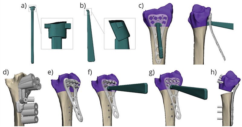
Figure 1. The shim instrument top (a) and lateral (b) view, and its positioning when the plate is fixated with the screws prior to reduction (c). The process of using the shim instrument is depicted in the bottom row of images (d–h). First, a drill guide (d) is used to aid in drilling screw holes, and another guide is used to guide the cutting; once the bone is cut, a plate is attached to the distal part of the bone, and screws are inserted but left unlocked (e); a shim instrument is inserted through the plate column to fit between the bone and the plate (f); the screws are then locked in position, while the shim instrument helps to hold the plate at the desired angle (g); the shim instrument is removed, and the bone is reduced by fixating the plate proximally (h).
During surgery, after drilling and performing the osteotomy, the screws in the distal fragment were placed, but not locked. Then, the shim instrument was placed between the bone and the plate to support the plate at the correct angle, while the screws were advanced and locked, as visualized in Figure 1e–h. The plate position was planned in such a manner that the distal edge had two contact points on the bone. This secured the rotational position of the plate.
Evaluation of surgical and radiographic parameters
Surgical details, such as the use of bone grafts and division of the brachioradialis tendon, were documented. In addition, we assessed if there was any bone contact between the proximal and distal radius segments after fixation. The planned maximal distraction was measured on the dorsal side of the radius in the virtual model.
Since the correction was 3D planned, the radiographic parameters were not measured on 2D radiographs. To compare the volar tilt, radial inclination, and ulnar variance of the preoperative, planned, and postoperative radius and ulna of each patient, the parameters were measured in MIS on the 3D models. The volar tilt was measured between a line drawn from the most volar point on the teardrop to a point on the dorsal edge of the radius in the sagittal plane and a plane perpendicular to the central axis of the radius. The central reference point (CRP) [16] was defined in the middle of the rim between the lunate fossa and the sigmoid notch. The radial inclination was measured between a line drawn from the CRP to the tip of the styloid and the perpendicular plane to the central axis. The ulnar variance was measured as the distance between the perpendicular plane to the central axis of the radius with the origin at the CRP and a parallel plane with the origin on the distal surface of the ulnar head.
3D Evaluation of the fixation method
To assess the accuracy of the fixation method, the patients were scanned within 1 week after the surgery with the same CT protocol as the preoperative scans. The built-in metal artifact reduction available for the GE Healthcare CT scanner was applied to the images. The postoperative CT images were segmented, and postoperative models were created and compared to the respective virtual plans. The postoperative positions of the distal radius fragment, the plate, and the screws were assessed with respect to the virtual plan. The screw angles were further analyzed with respect to the distal radius fragment and the plate. The position of the drill and cutting guide during the surgery was examined by looking at the displacement of all points where the screws enter the bone.
The position errors in the postoperative models were calculated by extracting the transformation matrix between the postoperative models and the respective planned models. The models were aligned using the Iterative Closest Point algorithm [17]. The transformation matrix provided us with rotation and translation measures in X, Y, and Z axes, according to the predefined coordinate system.
The axes of the translation and rotation were defined to reflect established radiological parameters in 3D space [16] (Figure 2). The origin of the coordinate system was defined at the CRP. The Z-axis was parallel to the central axis of the distal radius. The central axis of the radius was defined as the section between the center plane of the radius segment between 3 and 5 cm from the CRP in the lateral and anteroposterior projection [18,19]. The X-axis extended from the origin to the projection of the tip of the radial styloid, perpendicularly to the Z-axis. Finally, the Y-axis was orthogonal to the Z- and X-axes. In the coordinate system, the translation along the Z-axis corresponds to the radial length and, in case of an unchanged ulna, to the ulnar variance. The rotation around the X-axis corresponds to the volar tilt and the rotation in the Y-axis to the radial inclination. Positive rotation around the X-axis indicates an increase in volar tilt; around the Y-axis, an increase in radial inclination; and around the Z-axis, an increase in pronation deformity.

Figure 2. The coordinate system used for the analysis. The black dot, which is the central reference point (CRP), is located on the rim between the lunate fossa and the sigmoid notch. CRP is used as the origin of the coordinate system. The red dot indicates the tip of the radial styloid.
For each patient, the distal radius residual correction error was extracted from the transformation matrix by aligning the articular surface of the postoperative model to the planned model.
Because the postoperative model of the plate and the screws contained metal artifacts, we used the STL model of the plate and aligned it to the segmented plate model from the postoperative CT. For each screw, a central axis was created, and the point where the axis entered the bone was marked. From the axis and the entrance point, virtual cylinders were created for each postoperative screw with a diameter equal to the diameter of the planned screw.
To assess the angle error of the distal screws with respect to the plate, the planned plate model with screws (Figure 3a) was first aligned to the postoperative position of the plate. The transformation between the postoperative and planned screw cylinders was measured. The mean error across all screws represents the fixation error of the screws to the plate and indicates how well the shim instrument fulfilled its function, presuming that the guide position was correct (Figure 3b).
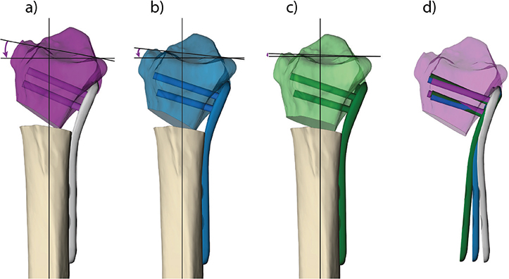
Figure 3. Contributing factors to the loss of volar tilt. The purple radius fragment is the planned correction and the correct position of the screws and plate; the planned volar tilt is shown (a). The blue model represents the loss in volar tilt when the plate was not fixed at the correct angle to the screws (b). The screws have the same position in relation to the distal radius, but there is a loss in the angle to the plate. The green model shows the final postoperative result (c). The plate and screws have the same position as the blue model, but the distal radius has settled under the pressure exerted during reduction, resulting in perceived screw migration. The loss in angle between the plate and the distal radius fragment is visualized when the planned correction of the distal radius depicted in the purple model is aligned with the blue and green models (d).
The error of the distal screw position within the bone was measured by first aligning the postoperative distal radius fragment with the screws to the planned distal radius position and then measuring the transformation between each screw cylinder and the planned position. This transformation (mean rotation of all screws around the X-axis) represented the migration of the screws in the distal radius fragment, presuming that the guide position was correct (Figure 3c).
The error in the position of the proximal screws was measured in the same way as the angle error of the distal screws. The proximal part of the plate was always fixed with one cortical screw in the sliding hole and two fixed-angle screws in the most proximal holes. As the highest force is exerted on the cortical screw during reduction, we observed a large displacement of this screw. For this reason, only the two most proximal fixed-angle screw transformations were measured.
The postoperative plate position in relation to the distal radius fragment was measured by first aligning the postoperative distal radius with the plate to the planned distal radius position and then measuring the transformation between the postoperative and the planned plate position. This error (rotation around the X- and Y-axes, and translation along the Z-axis) reflects the displacement of the distal radius fragment in relation to the plate position (Figure 3d).
Ethics
This study was approved by the Swedish Ethics Review Board (DNR:2021-01974). Participants received oral and written information about the study before giving written consent to participate.
Results
Surgical and radiographic parameters
The shim instrument was used in five surgeries (Table 1). The radiographic assessment showed good adherence to the surgical plans in terms of ulnar variance and radial inclination. However, volar tilt measurements performed within 1 week after surgery showed greater deviation from the surgical plans compared to radial inclination and ulnar variance.
3D analysis of the errors in the fixation method
Error in volar tilt. The total error in volar tilt is determined by the error of the screws in relation to the plate and the error of the screws in relation to the bone. This is illustrated in Figure 3.
Across the five surgeries, the mean absolute error in the rotation around the X-axis was 6.1°. In one patient, the absolute error was 9.5° (Table 2). In all patients, volar tilt values correspond to the negative error of the plate after first reversing the distal radius fragment to the planned position. The influence of the shim instrument on the distal radius correction error was not consistent across the patients (Table 2). The magnitude of the distal screw angle error around the X-axis with respect to the plate was below 5°. Settling of the bone on the screws was an important contributor to volar tilt loss. The combined loss in volar tilt due to the screw error in the bone and that in the plate – which indicates the total error around the X-axis – corresponds well to the distal radius volar tilt error.
| Patient ID | Distal radius error (°) | Plate error after reversing the distal radius (°) | Distal screw error in the bone*= settling (°) | Distal screw error vs. the plate* (°) | Total rotation error around the X-axis (°) |
| 1 | -4.4 | 5.0 | 1.1 ± 2.1 | -3.3 ± 2.2 | 4.5 ± 0.4 |
| 2 | -5.6 | 5.9 | 4.5 ± 2.5 | 0.8 ± 3.0 | 3.7 ± 3.7 |
| 3 | -5.8 | 6.4 | 4.9 ± 1.9 | 0.2 ± 1.9 | 5.0 ± 0.8 |
| 4 | -9.5 | 8.5 | 3.8 ± 2.4 | -4.8 ± 2.5 | 8.5 ± 0.2 |
| 5 | -5.4 | 4.4 | 3.1 ± 1.5 | -1.4 ± 1.5 | 4.6 ± 6.0 |
| Mean** | 6.1 | 6.1 | 3.5 | 2.1 | 5.3 |
| The values correspond to the error (± standard deviation) in rotation around the X-axis (°) for the distal radius, the plate, and the distal screws. *Values calculated without outliers (for individual screw error values, see supplementary material S1). **The mean calculated based on the absolute values. | |||||
Errors in radial inclination and ulnar variance. Analysis of the radial inclination error showed good adherence of the corrections to the surgical plans with the mean absolute error of rotation around the Y-axis of 1.6° (Table 3). The mean absolute rotation error of the plate position around the Y-axis exceeded 2°. In one patient, we observed a -4.5° error in plate position, which was likely caused by the rotation of the guide during drilling combined with the effect of fixation of the plate under tension (Figure 4). The errors in the plate and guide positioning did not appear to affect the distal radius error consistently across the patients.
| Patient ID | Distal radius error | Plate error | Guide error | ||||||
| Rotation (°) | Translation (mm) | Rotation (°) | Translation (mm) | Rotation (°) | Translation (mm) | ||||
| Y | X | Z | Y | X | Z | Y | X | Z | |
| 1 | –1.3 | 1.1 | –0.4 | –4.5 | –1.4 | 1.8 | –3.1 | 1.6 | 1.8 |
| 2 | 1.9 | 0.4 | –1.2 | –1.8 | 0.1 | 0.7 | –2.1 | 0.2 | 0.8 |
| 3 | –1.5 | 1.0 | –0.5 | –2.2 | –0.5 | 0.1 | –0.6 | 0.5 | –0.2 |
| 4 | –2.4 | 0.3 | –0.1 | –2.4 | –0.2 | 0.4 | –1.9 | 0.1 | 0.2 |
| 5 | –0.8 | 0.6 | –0.8 | –2.2 | –0.4 | 0.4 | –1.5 | 0.4 | 0.7 |
| Mean** | 1.6 | 0.7 | 0.6 | 2.6 | 0.5 | 0.7 | 1.8 | 0.6 | 0.7 |
| The values correspond to the error in rotation around the Y-axis (°) and translation along the X- and Z-axis (mm) for the distal radius, the plate, and the guide. **The mean calculated on the absolute values. | |||||||||
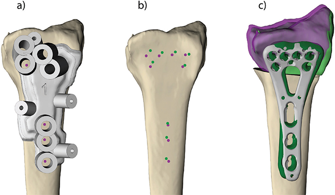
Figure 4. Positioning the drill guide (a) – images from the patient with the largest plate rotation error around Y-axis (patient 1). The purple dots represent the planned entrance holes for the screws, and the green dots represent the postoperative drill holes (b). The postoperative result (green) is projected onto the planned correction (purple) (c). The grey plate is the planned plate position, and the green plate is the postoperative plate position (c). Note that the guide error affects the plate error but does not affect the distal radius correction error to the same degree.
The error in translation along the Z-axis, corresponding to the ulnar variance, showed good adherence to the plan, with a mean absolute error of 0.6 mm (Table 3). A relatively high error was observed in the guide and plate position for patient 1. These deviations, however, did not influence the result of the correction since the guide translation is the same in both the proximal and distal fragments.
Errors in proximal screw fixation. The position of the proximal, fixed-angle screws after surgery compared to the virtual plan is presented for each patient in Table 4. These errors are a result of the errors in the guide position and the errors in screw fixation to the plate due to the variable angle locking system.
| Patient ID | Rotation X (°) | Rotation Z (°) | Translation X (mm) | Translation Z (mm) | ||||
| PS1 | PS2 | PS1 | PS2 | PS1 | PS2 | PS1 | PS2 | |
| 1 | –0.4 | 1.2 | 3.4 | 2.3 | –0.6 | –0.9 | 1.2 | 1.2 |
| 2 | 1.9 | 2.3 | –1.9 | –0.5 | –1.2 | –1.4 | –0.1 | 0.1 |
| 3 | 3.5 | 0.6 | –1.5 | 2.3 | 0.1 | –0.1 | –1.1 | –1.1 |
| 4 | 0.4 | 2.0 | 0.2 | 2.3 | –0.8 | –1.0 | –0.3 | –0.4 |
| 5 | 4.2 | 3.3 | 0.4 | –2.0 | –0.3 | –0.6 | –0.3 | –0.3 |
| Mean** | 2.1 | 1.9 | 1.5 | 1.9 | 0.6 | 0.8 | 0.6 | 0.6 |
| The values correspond to the rotation error of the two proximal screws around the X- and Z-axes (°) and the translation error along the X- and Z-axes (mm). PS: proximal screw. **The mean calculated on the absolute values. | ||||||||
The errors in guide and plate position were highest in patients 1 and 3. These patients also had the most rotation in the proximal screws. This is a consequence of the plate not being fixed precisely where it was planned and drilled for. Patient 5 had a pronounced error in the rotation around the X-axis in the proximal screws, indicating that the screws were locked while pointing slightly distally during reduction. This led to the plate being fixed in a position more proximal than intended and could, therefore, explain the magnitude of loss in ulnar variance, which was 0.8 mm in this patient.
Discussion
In this study, we evaluated a patient-specific, 3D-printed shim instrument to aid in securing the volar locking plate at the appropriate angle during corrective osteotomy of malunited distal radius fractures. The support provided by the shim instrument was fairly good but not consistent across the five patients included in the study. We found that both the insufficient support of the shim instrument and the settling of the distal radius fragment during and after reduction contributed to the volar tilt loss in our cohort.
In the five patients included in this study, the observed correction had a mean absolute rotation error around the X-axis (volar tilt) of 6.1°. This error marginally exceeded the generally acceptable limit of 5° [1]. The analysis of the plate and screw positions after surgery provided us with insights into the causes of the error. The main factor determining the angle between the distal screws and the plate during fixation was the shim instrument since the plate was fixed to the distal fragment without tension. In two patients, the distal screw-to-plate rotation error around the X-axis was 3.3° and 4.8°, suggesting that the shim instrument did not provide sufficient support.
The misalignment during screw fixation might be due to the instrument and plate not being correctly positioned. Enhancing the instrument’s design by enlarging the shim’s footprint on the bone could provide better plate support. The direction of the drilling could theoretically be another contributing factor, which is determined by the position of the guide and tolerance in the drill cylinders of the guide. It is not possible to extrapolate the intraoperative drill direction from the postoperative CT in a reliable manner because they cannot be visualized directly. It is only possible to determine the position of the screws on the CT, and they could have shifted, mainly due to tension during and after reduction. For the sake of the analysis of the plate and screw positions, we assumed, therefore, that the drilling error was negligible.
We suspect that, apart from the distal screw angle in the plate (which is a function of the shim instrument), settling of the distal fragment contributed to correction errors around the X-axis. This has been described in osteoporotic bone [20]. The distal radius settles until the subchondral bone rests on the distal fixed-angle screws. In our analysis, settling of the distal radius after reduction is expressed as the error – ‘migration’ – of the screw position in the bone of the distal radius, assuming again that drilling was done correctly. In our population, the mean contribution to the loss of volar tilt was 3.5°. The rotation error around the X-axis of the distal radius agreed with the sum of the screw-in-plate angle error and the negative screw-in-bone angle error, supporting the theory that both the insufficient support of the shim instrument and bone settling contribute to the loss in volar tilt. In our cohort, the settlling of the distal osteoporotic bone was the main factor contributing to the loss of volar tilt. When combined with with inaccurate plate fixation, the settling of the bone lead to an unacceptable result in one patient (patinet 4). Planning of the distal screws in a more distal, subchondral position, could minimize the settling and improve the correction in patients with osteoporotic bone [20].
The error in radial inclination was mainly caused by tension during the reduction of the plate to the diaphysis. The proximal screws locked in a more angled position than planned because the tension prevented the plate from fully reaching the planned position. This is possible because the locking system allows for a variation of 15° [21]. Translations of the proximal screws are caused by guide position errors and, in the second place, by migration of the screws in osteoporotic bone. However, the migration is less pronounced than for the distal screws since the cortex is stronger in the diaphysis.
The generally accepted value for maximal distraction in distal radius osteotomy is 12 mm [22]. Even though we are not aware of any experimental evidence for this statement, we find this to be reasonable in clinical practice. Achieving this level of distraction during surgery is challenging without the assistance of patient-specific guides. In three patients (2, 3, and 5), our planning resulted in distraction values close to or slightly exceeding 12 mm. Given the relatively low ulnar variance error in these cases, we can infer that achieving planned distraction may be facilitated by 3D surgical planning and patient-specific guides, as surgeons are more likely to aim for and achieve the planned distraction with the predrilled holes compared to an approach without 3D printed guides.
Our shim instrument did not always provide sufficient support to fixate the distal screws correctly. Despite this finding, we believe the concept of patient-specific support is sound to assist volar plate fixation during corrective osteotomy of a malunited distal radius fracture. Another support design has been investigated by Roner et al. [5], who developed a ramp guide to hold the plate at the correct angle during drilling and fix the plate distally. Similar to our study, Roner et al. found that the plate position adhered well to the virtual plan. Their ramp guide led to a mean flexion-extension (volar tilt) error of 1.97° in a group of eight patients. Although our study showed a larger mean correction error in volar tilt, 6.1°, the patients in our study were older (age range 63–74) than those included in the study of Roner et al. (age range 40–69) [5]. Older patients generally have softer bone quality and, therefore, are more prone to migration of the distal fragment under the forces exerted during reduction. Given that the settling of the bone likely contributed to volar tilt loss in our older study cohort, we cannot conclusively say whether the shim instrument provides poorer support than the ramp guide of Roner et al. [5].
The main limitation of the study design is the small cohort and the lack of a control group. Randomized studies with a larger cohort can provide a more precise estimation of the accuracy of the shim instrument compared to other designs for supporting the plate and free-hand fixation. Furthermore, long-term follow-up will be required to assess whether the radiographic results are maintained during healing and whether the correction errors have an impact on patient outcomes. Another limitation arises from metal artifacts in the post-surgery CT images. A more detailed analysis of the plate position is not possible with current imaging techniques, as the postoperative virtual models are severely affected by metal artifacts on the CT scans. These artifacts impacted the segmentation of the metal components, potentially introducing some level of inaccuracy in screw and plate positions. Nevertheless, we do not believe these inaccuracies had a substantial influence on the results and the conclusions of this study. There are several limitations to the design of the shim instrument as well. Our instrument can only be used with a two-column plate as it must be positioned in the opening between columns to ensure the stability of the plate when the screws are being tightened. Positioning a shim from the ulnar or radial side will not guarantee the stability of the plate during fixation. The shim instrument must also be held by the surgeon while tightening the screws, which adds another instrument to handle. While we did not attempt to systematically assess surgeons’ impressions of the shim instruments, they reported satisfaction with it. It may be partly attributed to their direct involvement in its design. This highlights the benefit of in-house design and 3D printing for patient-specific instruments, as it allows for immediate adjustments based on the surgeon’s feedback and experience.
Our results provide a few directions for future research to explore. Other techniques for plate positioning on the distal fragment can be tested, as well as different solutions to reduce tension on the reduction. Both the problem of the plate fit and the tension of the reduction can be addressed by using patient-specific plates. In conclusion, the correction error resulting from our shim instrument was not consistent across patients but generally fell within the acceptable limit of 5°. The shim instrument was not the only factor that impacted the volar tilt error in the cohort. Distal radius settling, which largely depends on the amount of force exerted during reduction and on the quality of the bone, contributed to correction errors.
Acknowledgments
We would like to thank Johan Andersson for help with creating images for this work. This study was financed by grants from the Swedish state under the agreement between the Swedish government and the county councils, the ALF agreement.
ORCID
Emilia Gryska  http://orcid.org/0000-0002-7912-2232
Katleen Libberecht http://orcid.org/0009-0003-4030-106X
Peter Axelsson http://orcid.org/0000-0003-2318-6824
Anders Björkman http://orcid.org/0000-0003-0600-1365
Charlotte Stor Swinkels http://orcid.org/0009-0005-8481-7935
Per Fredrikson http://orcid.org/0000-0001-9753-8787
References
[1] Prommersberger KJ, Van Schoonhoven J, Lanz UB. Outcome after corrective osteotomy for malunited fractures of the distal end of the radius. J Hand Surg. 2002;27(1):55–60. https://doi.org/10.1054/JHSB.2001.0693
[2] Vroemen JC, Dobbe JGG, Strackee SD, et al. Positioning evaluation of corrective osteotomy for the malunited radius: 3-D CT versus 2-D radiographs. Orthopedics. 2013 Feb;36(2):e193–e199. https://doi.org/10.3928/01477447-20130122-22
[3] von Campe A, Nagy L, Arbab D, et al. Corrective osteotomies in malunions of the distal radius: do we get what we planned? Clin Orthop Relat Res. 2006;450:179–185. https://doi.org/10.1097/01.blo.0000223994.79894.17
[4] de Muinck Keizer RJO, Lechner KM, Mulders MAM, et al. Three-dimensional virtual planning of corrective osteotomies of distal radius malunions: a systematic review and meta-analysis. Strat Traum Limb Recon. 2017;12(2):77–89. https://doi.org/10.1007/s11751-017-0284-8
[5] Roner S, Carrillo F, Vlachopoulos L, et al. Improving accuracy of opening-wedge osteotomies of distal radius using a patient-specific ramp-guide technique. BMC Musculoskeletal Disorders. 2018;19(1):374. https://doi.org/10.1186/s12891-018-2279-0
[6] Ma B, Kunz M, Gammon B, et al. A laboratory comparison of computer navigation and individualized guides for distal radius osteotomy. Int J CARS. 2014;9(4):713–724. https://doi.org/10.1007/s11548-013-0966-8
[7] Oka K, Murase T, Moritomo H, et al. Accuracy of corrective osteotomy using a custom-designed device based on a novel computer simulation system. J Orthop Sci. 2011;16(1):85–92. https://doi.org/10.1007/s00776-010-0020-4
[8] Sariali E, Kajetanek C, Catonné Y. Comparison of custom cutting guides based on three-dimensional computerized CT-scan planning and a conventional ancillary system based on two-dimensional planning in total knee arthroplasty: a randomized controlled trial. Int Orthop. 2019;43(11):2529–2538. https://doi.org/10.1007/s00264-019-04357-3
[9] Orbay J. Volar plate fixation of distal radius fractures. Hand Clin. 2005;21(3):347–354. https://doi.org/10.1016/j.hcl.2005.02.003
[10] Ring D, Roberge C, Morgan T, et al. Osteotomy for malunited fractures of the distal radius: a comparison of structural and nonstructural autogenous bone grafts. J Hand Surg Am. 2002;27(2):216–222. https://doi.org/10.1053/jhsu.2002.32076
[11] Dobbe JGG, Vroemen JC, Strackee SD, et al. Patient-tailored plate for bone fixation and accurate 3D positioning in corrective osteotomy. Med Biol Eng Comput. 2013;51(1–2):19–27. https://doi.org/10.1007/s11517-012-0959-8
[12] Omori S, Murase T, Kataoka T, et al. Three-dimensional corrective osteotomy using a patient-specific osteotomy guide and bone plate based on a computer simulation system: accuracy analysis in a cadaver study. Int J Med Robot Comput Assist Surg. 2014;10(2):196–202. https://doi.org/10.1002/rcs.1530
[13] Schindele S, Oyewale M, Marks M, et al. Three-dimensionally planned and printed patient-tailored plates for corrective osteotomies of the distal radius and forearm. J Hand Surg. 2024;49(3):277.e1–277.e8. https://doi.org/10.1016/j.jhsa.2022.06.021
[14] Regulation (EU) 2017/745 of the European Parliament and of the Council of 5 April 2017 on medical devices, amending Directive 2001/83/EC, Regulation (EC) No 178/2002 and Regulation (EC) No 1223/2009 and repealing Council Directives 90/385/EEC and 93/42/EEC [Internet]. [cited 2017 May 5]. Available from: http://data.europa.eu/eli/reg/2017/745/2017-05-05/eng
[15] CT scan protocol – osteotomies – upper extremity – English [Internet]. [cited 2023 May 25]. Available from: https://assets-eu-01.kc-usercontent.com/8ff24b0e-57a3-0157-62d1-fa4ac9734eb5/df9e5f44-7ec7-4f0b-b964-ecd50ee45de5/CT%20Scan%20Protocol%20-%20Osteotomies%20-%20Upper%20Extremity%20-%20English%20-%20L-102000-01.pdf
[16] Medoff RJ. Essential radiographic evaluation for distal radius fractures. Hand Clinics. 2005;21(3):279–288. https://doi.org/10.1016/j.hcl.2005.02.008
[17] Besl PJ, McKay ND. Method for registration of 3-D shapes. In: Sensor Fusion IV, editor. Control paradigms and data structures [Internet]. SPIE; 1992 [cited 2023 Oct 16]. p. 586–606. Available from: https://www.spiedigitallibrary.org/conference-proceedings-of-spie/1611/0000/Method-for-registration-of-3-D-shapes/10.1117/12.57955.full
[18] Kreder HJ, Hanel DP, McKee M, et al. X-ray film measurements for healed distal radius fractures. J Hand Surg Am. 1996;21(1):31–39. https://doi.org/10.1016/S0363-5023(96)80151-1
[19] Suojärvi N, Tampio J, Lindfors N, et al. Computer-aided 3D analysis of anatomy and radiographic parameters of the distal radius. Clin Anat. 2021;34(4):574–80. https://doi.org/10.1002/ca.23615
[20] Orbay JL, Fernandez DL. Volar fixed-angle plate fixation for unstable distal radius fractures in the elderly patient. J Hand Surg Am. 2004;29(1):96–102. https://doi.org/10.1016/j.jhsa.2003.09.015
[21] Vlachopoulos L, Schweizer A, Graf M, Nagy L, Fürnstahl P. Three-dimensional postoperative accuracy of extra-articular forearm osteotomies using CT-scan based patient-specific surgical guides. BMC Musculoskel Disord. 2015 Nov 4;16:336. https://doi.org/10.1186/s12891-015-0793-x
[22] Prommersberger KJ, Pillukat T, Mühldorfer M, et al. Malunion of the distal radius. Arch Orthop Trauma Surg. 2012;132(5):693–702. https://doi.org/10.1007/s00402-012-1466-y