ORIGINAL RESEARCH ARTICLE
In vivo virtual investigation of the implant location for scaphoid fractures
Ren-Guo Xie, MD, PhDa,b† and Dong-Sheng Ji, MDb†
aDepartment of Hand Surgery, Shanghai First People’s Hospital, School of Medicine, Shanghai Jiao Tong University, Shanghai, China; bDepartment of Hand Surgery, Rugaogang Hospital, Jiangsu, China
ABSTRACT
Introduction: Scaphoid fractures still have high rate of nonunion, mainly due to the tenuous blood supply and only primary bone healing. Rigid fixation facilitates this kind of bone healing and is considered as vital as protection of the blood supply. The optimal implant (screw) location should meet the requirements for researcher’s biomechanical findings on fracture stability.
Materials and methods: Raw CT-scanned data of eight volunteers’ wrists were imported into Mimics. The 3D scaphoid was segmented out and calculated, then opened in Geomagic Studio. Four fracture planes (proximal, oblique waist, horizontal waist and distal) simulating common broken scaphoid were created. Mimicking scaphoid implants (screws), the longest, the sub-longest, and central and eccentric cylinders perpendicular to each fracture plane were created. Whole and inside-fragmental length, and the relative location of each cylinder were measured and analyzed.
Results: The longest (28.5 ± 1.6 mm) cylinder was significantly longer than the sub-longest (25.4 ± 1.4 mm). Several eccentric perpendicular cylinders (so short or cutting out of the scaphoid) couldn’t be created. Some proximal inside-fragmental lengths ranged from 3.0 to 5.1 mm. Several central perpendicular cylinders intersected with the longest one. Several central and eccentric perpendicular cylinders were outside of the proximal scaphoid non-contact region.
Conclusion: The results of this study showed that scaphoid fracture images from CT scan can be calculated and yield the optimal implant location.
KEYWORDS: implant; in vivo; measurement; scaphoid fracture; virtual investigation
Citation: Journal of Plastic Surgery and Hand Surgery 2026; 61: 182–188. DOI: https://doi.org/10.2340/jphs.v61.46484.
Copyright: © 2026 The Author(s). Published by MJS Publishing on behalf of Acta Chirurgica Scandinavica. This is an Open Access article distributed under the terms of the Creative Commons Attribution 4.0 International License (http://creativecommons.org/licenses/by/4.0/), allowing third parties to copy and redistribute the material in any medium or format and to remix, transform, and build upon the material, with the condition of proper attribution to the original work.
Received: 26 January 2026; Accepted: 24 June 2026; Published: 3 August 2026.
CONTACT: Ren-Guo Xie, MD, PhD renguo.xie@gmail.com; 13862906768@163.com Department of Hand Surgery, Shanghai First People’s Hospital, School of Medicine, Shanghai Jiao Tong University, 650 New Songjiang Road, Songjiang, Shanghai 201620, China
†Ren-Guo XIE and Dong-Sheng JI are co-first authors.
Competing interests and funding: The authors report there are no competing interests to declare.
Introduction
Despite optimal treatment, scaphoid fractures are notorious for their high rate of non-union, approximately 5–20% after conservative management and around 15.5% overall [1–5]. The surgeon scientists have been struggling to improve the remedy. Besides focusing on the operative approach to reduce the risk of injury to the tenuous blood supply of the scaphoid, researchers also have been making some progress in the biomechanical stability of the fracture, the same importance considered as the preservation of the blood flow to the unique bone [6]. Since scaphoid fractures lack the capacity to form callus, primary bone healing remains the only mode of union [7]. Therefore, rigid fixation that maintains fragment stability is essential to facilitate this healing process. Headless cannulated screw implanted to synthesize the fragments is becoming mainstream [8, 9], and the plate were usually preserved for the complex fracture with distal pole fragmentation, with comminution and non-union after prior failure of screw fixation [10]. The screw placed along the central zone of the scaphoid would be longer inside than other eccentric placements, and the longer purchase of the fragment meant the more stability. The superior biomechanical characteristic of the screw in central position were confirmed through some studies [11, 12]. Subchondral 2-mm zone of the scaphoid had the greatest bone density, while the inner regions had significantly lower, including the lowest central zone [13, 14]. Two screws provide greater biomechanical stability and have higher union rate [15, 16]. Multiple Kirschner wires had the advantages of short union time, less demanding, and less expensive than single screw implant [17]. A mechanical study for oblique scaphoid fractures showed the same stability of the screw perpendicular to the fracture line and parallel to the long axis of the scaphoid [18]. Screw malpositioning could also cause median nerve injury [19]. During scaphoid fracture surgery, the screw placement, including its starting point and direction, has typically been determined by the surgeon’s preference and often appeared arbitrary. It might be a little far from the need of modern accurate surgery. Nowadays, CT is becoming popular in complicated diagnosis and follow-up treatment for scaphoid fractures [2, 20]. Jung et al. also analyzed the 3D scaphoid implant model to simplify the data interpretation on anteroposterior and lateral radiographs, thereby providing safer guidance for screw positioning [21]. We hypothesized that there would exist the optimal implant location for specific scaphoid facture planes, which would meet the requirements for the researcher’s findings, sufficient purchase and reasonable relationship with the fracture, instead of surgeon’s subjective opinion, based on virtually analyzing the CT data.
Materials and methods
We used the same raw data as our previous study [22]. Eight of our colleagues took part in this investigation as the volunteers, including six hand surgeons and two radiologists. Our hospital review board approved this study (2019KY016). All volunteers were male, and mean age was 36 years (range, 31–44 years). Clinical examinations didn’t invoke any symptom and any impediment of the carpal motion, posteroanterior and lateral radiographs didn’t show any abnormal skeletons, and no any remarkable disorder history was recalled in their upper limbs.
A computed tomography (CT) scanner (SOMATOM Definition Flash, Siemens Medical, Forchheim, Germany) was used to obtain the volume images for the volunteers’ wrists at tube setting of a maximum of 120 kVp and 100 mA and a slice thickness of 0.6 mm.
Volunteers were positioned prone on the CT table, with the right arm stretched over the head, the shoulder abducted slightly and flexed at about 120 degrees, the elbow flexed slightly, and the wrist centered in gantry. During CT scanning, the volunteer’s position was maintained with several pillows placed under the chest and arm to ensure comfort, while only the wrist remained unconstrained.
Subjects actively moved their wrist to six extreme positions: flexion, extension, radial deviation, ulnar deviation, pronation and supination. Contiguous scanning was performed from the distal part of the radius and ulna to the middle part of the metacarpus. Each position was scanned independently for 7 seconds.
The wrist extreme position of palmar flexion was only chosen for our study. We used Mimics 21.0 (Materalise, Leuven, Belgium) and a reverse-engineering software (Geomagic Studio 2013, Geomagic Inc., North Carolina, USA) to deal with the CT DICOM files. This study was further step toward continuing our previous non-contact regions of proximal scaphoid in the stage of wrist extreme position of palmar flexion [22].
All features except for the scaphoid and confined so-called non-contact regions were concealed, and four fracture planes were created. The proximal plane was created with two points (palmar and dorsal) just proximal to the volar and dorsal points on midcarpal lunate side, and the third point defined (through which formed an approximately horizontal plane). Oblique waist plane was created with three points on the dorsal ridge. Horizontal waist plane, through the central part of orientation from the proximal to the distal, was created approximately perpendicular to the scaphoid long axis. The distal plane was created with three approximately horizontal points onto the distal 1/3 part (Figure 1).
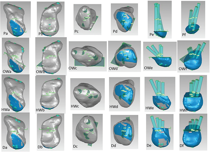
Figure 1. The proximal plane (row1) was created with two points (palmar and dorsal) just proximal to the volar and dorsal points on midcarpal lunate side, and the third point defined (through which formed an approximately horizontal plane). Oblique waist plane (row2) was created with three points on the dorsal ridge. Horizontal waist (row3), through the central part of orientation from the proximal to the distal, a plane was created perpendicular to the scaphoid long axis. The distal plane (row4) was created with three approximately horizontal points onto the distal 1/3 part. Four cylinders regarding the different fracture plane mimicking the implants (screw) were created, respectively (e, f). P = proximal, OW = oblique waist, HW = horizontal waist, D = distal. Six typical frames (a, b, c, d, e, and f) were screenshotted to analyze. Overall viewing of frames a and b, all cylinders were completely inside the scaphoid and not cutting out of the cartilage. On distal polar view (c), end points of all cylinders were clear. On proximal polar view (d), we could check whether the start point was inside the non-contact region (blue area). Removing the distal fragment, relative position of the longest, sub-longest, central perpendicular, and eccentric perpendicular cylinders with the fracture plane, and whether the cylinders would interfere with each other could be analyzed (e, f).
And then, cylinders with a diameter of 3 mm (mimicking outer diameter of a commonly used cannulated screw) were created. Their two polar (the distal and the proximal) central points were defined on the osseous surface in the scaphoid. The longest cylinder was created with two points (the distal and the proximal) and the diameter. The distal point was the apex of the scaphoid tubercle, and the proximal point was 2-mm radial deviation to the scapholunate ligament and 2-mm dorsal deviation to the proximal scaphoid apex. The sub-longest cylinder was also created with two points and the diameter. The distal point was the central point of the distal polar, and the proximal point was just radial and dorsal deviation of the proximal point in the longest cylinder in order that the sub-longest cylinder just didn’t intersect with the longest cylinder. Two cylinders perpendicular to each fracture plane were created with its base point, direction vector, height and diameter as follows. The central perpendicular cylinder, of which base point was the central one of the outline onto the fracture plane, and height was adjusted to make sure two polar (the distal and the proximal) central points were defined onto the osseous surface. The eccentric perpendicular cylinder, whose base point lay on the fracture plane, was designed to satisfy the following three conditions as much as possible: long fragment purchase, no cut-out from the osseous surface, and the proximal end located within non-contact regions (Figure 1).
Total cylinder length and its fragmental (inside the distal or the proximal) length regarding to different fracture planes were recorded. The fragmental (inside the distal or the proximal) length of the orthographic projections regarding the fracture plane of the longest and sub-longest cylinders were also recorded. Whether the cylinders intersected with each other were observed and recorded. Whether the proximal end of the cylinders was inside the non-contact regions of proximal scaphoid and the trajectory of the cylinders was inside the central zone regarding the fracture planes of the scaphoid were also observed and recorded (Figure 1). We also recorded the scaphoid morphological types, full (Type I) and slender (Type II) as mentioned by Morsy et al. [23].
Simple statistical method (paired-t test) performed using Excel 2013. The mean, standard deviation, and count of selected parameters were calculated, and a significance level of p < 0.05 was set.
Results
From gross inspection, six volunteers (No.1, 2, 3, 4, 7, 8) had full or type I scaphoids and two (No.5, 6) had slender or type II scaphoids. The longest cylinder (28.5 ± 1.6 mm) was significantly longer than the sub-longest cylinder (25.4 ± 1.4 mm) (p < 0.01), of which the vertical components (26.1 ± 2.1 mm vs. 24.5 ± 1.7 mm) showed the same tendency (p < 0.01) (Table 1). Their proximal ends all located inside non-contact regions of the scaphoid proximal surface (Table 4), and no intersection between these two cylinders was found inside the scaphoid and onto its surface (Tables 2, 3, and 5). Regarding the proximal fracture plane, the proximal part (inside the proximal fracture fragment) of the longest cylinder was 5.1 ± 0.8 mm, and the distal part (inside the distal fracture fragment) was 23.5 ± 2.1 mm, and their vertical components were 4.6 ± 0.7 mm (proximal) and 21.4 ± 2.5 mm (distal). The proximal part of the sub-longest cylinder was 3.0 ± 1.1 mm, and the distal part was 22.4 ± 1.9 mm, and their vertical components were 2.9 ± 1.0 mm (proximal) and 21.6 ± 2.0 mm (distal). The central perpendicular cylinder was 19.9 ± 8.6 mm, of which the proximal part was 4.2 ± 0.6 mm and the distal part was 15.7 ± 8.5 mm. The eccentric perpendicular cylinder was 20.7 ± 6.0 mm, of which the proximal part was 3.5 ± 1.1 mm and the distal part was 17.2 ± 6.1 mm. There were no available positions for the eccentric perpendicular cylinders in two volunteers (Table 1). Their proximal ends were all located inside non-contact regions of the scaphoid proximal surface (Table 4). The central perpendicular cylinder intersected with the longest cylinder, and the eccentric perpendicular cylinder didn’t (Tables 2, 3, and 5).
Regarding the oblique waist fracture plane, the proximal part of the longest cylinder was 15.2 ± 1.3 mm, and the distal part was 13.3 ± 2.3 mm, and their vertical components were 10.6 ± 1.2 mm (proximal) and 9.3 ± 1.8 mm (distal). The proximal part of the sub-longest cylinder was 11.1 ± 1.0 mm, and the distal part was 14.4 ± 1.4 mm, and their vertical components were 8.9 ± 1.2 mm (proximal) and 11.5 ± 1.3 mm (distal). The central perpendicular cylinder was 18.7 ± 3.5 mm, of which the proximal part was 9.1 ± 1.4 mm and the distal part was 9.6 ± 3.0 mm. The eccentric perpendicular cylinder was 17.7 ± 3.3 mm, of which the proximal part was 9.3 ± 1.9 mm and the distal part was 8.4 ± 2.8 mm. The vertical components of the longest and the sub-longest cylinders were significantly longer than the central and eccentric perpendicular cylinders (p < 0.01, Table 1). There was no available position for the eccentric perpendicular cylinder in one volunteer (Table 1). The proximal ends of three central perpendicular cylinders and all seven eccentric perpendicular cylinders were located inside non-contact regions of the scaphoid proximal surface (Table 4). The central perpendicular and the eccentric perpendicular cylinders didn’t intersect with the longest cylinders (Tables 2, 3, and 5).
Regarding the horizontal waist fracture plane, the proximal part of the longest cylinder was 14.0 ± 1.0 mm, and the distal part was 14.5 ± 1.8 mm, and their vertical components were 13.0 ± 1.0 mm (proximal) and 1.5 ± 1.8 mm (distal). The proximal part of the sub-longest cylinder was 11.8 ± 0.7 mm, and the distal part was 13.7 ± 1.1 mm, and their vertical components were 11.3 ± 0.8 mm (proximal) and 13.2 ± 1.0 mm (distal). The central perpendicular cylinder was 23.1 ± 2.6 mm, of which the proximal part was 10.5 ± 2.3 mm and the distal part was 12.6 ± 1.0 mm. The eccentric perpendicular cylinder was 23.4 ± 2.7 mm, of which the proximal part was 11.3 ± 1.8 mm and the distal part was 12.1 ± 1.9 mm. The vertical components of the longest and the sub-longest cylinders were significantly longer than the central perpendicular cylinders (p < 0.01, Table 1). There were no available positions for the eccentric perpendicular cylinders in three volunteers (Table 1). The proximal ends of seven central perpendicular cylinders and all five eccentric perpendicular cylinders were located inside non-contact regions of the scaphoid proximal surface (Table 4). Three central perpendicular and none of the eccentric perpendicular cylinders intersected with the longest cylinders (Tables 2, 3, and 5).
Regarding the distal fracture plane, the proximal part of the longest cylinder was 18.0 ± 0.9 mm, and the distal part was 10.6 ± 1.5 mm, and their vertical components were 17.1 ± 0.9 mm (proximal) and 10.1 ± 1.5 mm (distal). The proximal part of the sub-longest cylinder was 15.6 ± 0.9 mm, and the distal part was 9.8 ± 1.0 mm, and their vertical components were 15.4 ± 0.9 mm (proximal) and 9.7 ± 1.0 mm (distal). The central perpendicular cylinder was 24.5 ± 1.6 mm, of which the proximal part was 15.2 ± 1.4 mm and the distal part was 9.3 ± 1.0 mm. The eccentric perpendicular cylinder was 22.7 ± 1.1 mm, of which the proximal part was14.8 ± 1.6 mm and the distal part was 7.8 ± 0.9 mm. Only the vertical components of the longest cylinders were significantly longer than the central perpendicular cylinders (p < 0.05, Table 1). There were no available positions for the eccentric perpendicular cylinders in five volunteers (Table 1). All the proximal ends were located inside non-contact regions of the scaphoid proximal surface (Table 4). Two central perpendicular and none of the eccentric perpendicular cylinders intersected with the longest cylinders (Tables 2, 3, and 5).
The longest cylinders, mostly (six in eight) went through the central proximal fracture plane, and none through the central of other three fracture planes. Among the sub-longest cylinders, three out of eight passed through the central proximal and waist fracture planes, five out of eight through the central sulcus fracture plane, and six out of eight through the central sulcus fracture plane, and six in eight through the central distal fracture plane (Tables 5).
Discussions
The longest cylinder (28.5 ± 1.6 mm) and the sub-longest cylinder (25.4 ± 1.4 mm) were a little shorter than the anatomic scaphoid (31.3 ± 2.1 mm) by Heinzelmann AD et al. [24], owing to two different end points to measure. Six volunteers had full or type I scaphoids and two had slender or type II scaphoids, which was the similar observation to the literature [23].
Four planes were created on the 3D scaphoid models calculated from the CT raw data as aforementioned to simulate the most popular classification of scaphoid fractures, and in the light of recent biomechanical contribution to the scaphoid studies four cylinders mimicking the cannulated implants regarding every fracture plane were created for further measurement [12–16, 18]. Both the longest cylinder and the sub-longest cylinder were consistent with the principle that long purchase and central placement contribute substantially to interfragmentary stability [11, 12]. The central perpendicular cylinder and the eccentric perpendicular cylinder were based on the concept that a perpendicular implant would genenrate high compressive force [18]. If no intersection occurs, two cylinders would enhance compression of two fragments and resistance to interfragmental rotation.
Definition of ‘proximal’ in proximal scaphoid fracture affected the risk of non-union [25]. The inner proximal part length (3.0–5.1 mm) regarding our experimental proximal fracture plane was insufficient to maintain the fragment stability (Table 1), while considering the screw purchase inside the 2-mm subchondral region would yield effective stability [13]. Moreover, mechanical advantage from distal fragmentary long level arm would increase the proximal fragmental resistance to keep whole bone solidation. Interfacial micro-motion might occur and increase the risk of non-union. The cannulated implant would not be suitable for the proximal and especially very proximal scaphoid fracture.
About two-thirds scaphoid fractures occur in the waist area [26]. Regarding the non-displaced and mini-displaced scaphoid waist fractures, there are still no concrete evidence within the literature to prefer early operative intervention or conservative management in a cast [27–31]. While surgery for scaphoid fractures is indicated, physician should optimize implant location to improve the efficiency of rigid fixation. We simulated two fracture planes in the waist, via sulcus and almost transverse. Four cylinders had about 8 mm inside fragmental purchase, including the vertical component of the oblique (the longest and sub-longest) cylinders (Table 1). The proximal ends of all oblique cylinders were located within the non-contact area, whereas some of the perpendicular cylinders (central and eccentric) were not (Table 4). Except for the central perpendicular cylinder, none of the others were not all in the central part of the fracture plane (Table 5). While both cylinders went through the central part, they would intersect with each other (Tables 3 and 5). Our study demonstrated that two screws meeting the following conditions for scaphoid waist fractures could be put into practice. The screws should be introduced into the fragments through dorsal approach and no contact region, and there should be no intersection, and much inside purchase (oblique, and perpendicular or as perpendicular as possible). Preoperative CT data could be calculated to render the 3D model, through which we usually observed and simply analyzed visually to get the morphological information of the scaphoid fractures to make the operative plan. For conventional open surgery, visual registration could be guaranteed with the full exposure of the targeting tissue and organ. However, scaphoid was encompassed by the distal radius, the lunate, the capitate, the trapezium, and the trapezoid, which impeded the full exposure without damaging the adjacent structures. Moreover, the tenuous blood supply mainly originating from the dorsal septa limited full exposure at the surgeon’s discretion. We used the reverse engineering softwares, such as Geomagic Studio to virtualize optimum location of the implants, with the aim of minimizing or avoiding compromise to the aforementioned factors.. Currently, we could through mini-incision percutaneously insert implants monitored under fluoroscan. We anticipated much specific and accurate remedy with computer-aided navigation in accordance with our in vivo virtual investigation.
As for our simulated distal fracture, all cylinders had sufficient fragmental purchase, except for the eccentric perpendicular, of which five cases were not available. The distal scaphoid anatomically extending toward volar and radial side [32], and implant through dorsal approach and non-contact region orientating along with the long axis of the scaphoid might contribute to our findings.
Scaphoid was also named as navicular bone for its special shape, which adaptively resulted from kinematic role in wrist motion, articulations with the adjacent carpals and restriction by attached ligaments. Each scaphoid might exhibit some specific morphological feats [23, 33], and we physicians should take into consideration, the screw placement having good purchase and not cutting and penetrating the cartilage surface, especially in two screws implanted. While moving the wrist, scaphoid was forced and restrained to extend, flex, ulnar-deviate, radial-deviate, rotate, and sweep (changing the scaphoid centroid), which would result in need of multiple-directional resistance and constrain to the inter-fragmentary motion. Two screws not exactly perpendicular to fracture plane could be the optimal selection. In clinical practice, when two screws were preference, we would compromise among the precise central zone, the length as long as possible, and the perpendicularity to the fracture plane. No intersection with each other and sufficient purchase (vertical component to the fracture plane) would be taken in the mind.
With assistance of the reverse-engineering software (Geomagic Studio), we successfully simulated and analyzed the implant location in scaphoid fractures. We Physicians understand and master the relevant software could enhance the accurate surgical procedures. We should not only read the primary images, such as X-rays films and CT images but also use the software to simulate and analyze the patient-specific raw data.
Our study had some limitations. We did not randomize selection of the enrollees, and all volunteers were from the same age-span, all male and all doctors. The fracture planes were created with self-defined points and vectors, to mimic common clinical scaphoid fracture types. As for the specific analysis, these limitations might have little effect on the results and conclusions.
References
[1] Buijze GA, Bachoura A, Mahmood B, et al. Reevaluation of the scaphoid fracture: what is the current best evidence? Instr Course Lect. 2020;69:317–330.
[2] Clementson M, Björkman A, Thomsen NOB. Acute scaphoid fractures: guidelines for diagnosis and treatment. EFORT Open Rev. 2020;5(2):96–103. https://doi.org/10.1302/2058-5241.5.190025
[3] Mahmoud M, Koptan W. Percutaneous screw fixation without bone grafting for established scaphoid nonunion with substantial bone loss. J Bone Joint Surg Br. 2011;93(7):932–936. https://doi.org/10.1302/0301-620X.93B7.25418
[4] Reigstad O, Grimsgaard C, Thorkildsen R, et al. Long-term results of scaphoid nonunion surgery: 50 patients reviewed after 8 to 18 years. J Orthop Trauma. 2012;26(4):241–245. https://doi.org/10.1097/BOT.0b013e31821f940a
[5] Zura R, Xiong Z, Einhorn T, et al. Epidemiology of fracture nonunion in 18 human bones. JAMA Surg. 2016;151(11):e162775. https://doi.org/10.1001/jamasurg.2016.2775
[6] Dodds SD, Slade JF. A biomechanical assessment of scaphoid fracture repair. In: Slutsky DJ, Slade JF, editors. The scaphoid. New York: Thieme Medical Publishers, Inc; 2010. p. 16–21.
[7] Hackney LA, Dodds SD. Assessment of scaphoid fracture healing. Curr Rev Musculoskelet Med. 2011;4(1):16–22. https://doi.org/10.1007/s12178-011-9072-0
[8] Goodwin J, Castañeda P, Drace P, et al. A biomechanical comparison of screw and plate fixations for scaphoid fractures. J Wrist Surg. 2018;7(1):77–80. https://doi.org/10.1055/s-0037-1606123
[9] Gray RRL, Halpern AL, King SR, et al. Scaphoid fracture and nonunion: new directions. J Hand Surg. 2023;48(2_suppl):4S–10S. https://doi.org/10.1177/17531934231165419
[10] Leti Acciaro A, Lana D, Fagetti A, et al. Plate fixation in challenging traumatic carpal scaphoid lesions. Musculoskelet Surg. 2022;106(2):179–185. https://doi.org/10.1007/s12306-020-00689-1
[11] Dodds SD, Panjabi MM, Slade JF, 3rd. Screw fixation of scaphoid fractures: a biomechanical assessment of screw length and screw augmentation. J Hand Surg Am. 2006;31(3):405–413. https://doi.org/10.1016/j.jhsa.2005.09.014
[12] McCallister WV, Knight J, Kaliappan R, et al. Central placement of the screw in simulated fractures of the scaphoid waist: a biomechanical study. J Bone Joint Surg Am. 2003;85(1):72–77. https://doi.org/10.2106/00004623-200301000-00012
[13] Swanstrom MM, Morse KW, Lipman JD, et al. Variable bone density of scaphoid: importance of subchondral screw placement. J Wrist Surg. 2018;7(1):66–70. https://doi.org/10.1055/s-0037-1605381
[14] Ahrend MD, Teunis T, Noser H, et al. 3D computational anatomy of the scaphoid and its waist for use in fracture treatment. J Orthop Surg Res. 2021;16(1):216. https://doi.org/10.1186/s13018-021-02330-8
[15] Mandaleson A, Tham SK, Lewis C, et al. Scaphoid fracture fixation in a nonunion model: a biomechanical study comparing 3 types of fixation. J Hand Surg Am. 2018;43(3):221–228. https://doi.org/10.1016/j.jhsa.2017.10.005
[16] Quadlbauer S, Beer T, Pezzei C, et al. Stabilization of scaphoid type B2 fractures with one or two headless compression screws. Arch Orthop Trauma Surg. 2017;137(11):1587–1595. https://doi.org/10.1007/s00402-017-2786-8
[17] Hegazy G, Seddik M, Abd-Elghany T, et al. Treatment of unstable scaphoid waist nonunion with cancellous bone grafts and cannulated screw or Kirschner wire fixation. J Plast Surg Hand Surg. 2021;55(3):167–172. https://doi.org/10.1080/2000656X.2020.1856674
[18] Kılıç B, Çalışkan M, Agar A, et al. Comparison of two different screw trajectories in the treatment of oblique scaphoid fractures: a mechanical study on composite bone models. Jt Dis Relat Surg. 2021;32(2):377–382. https://doi.org/10.52312/jdrs.2021.15
[19] Starnoni M, Colzani G, De Santis G, et al. Median nerve injury caused by screw malpositioning in percutaneous scaphoid fracture fixation. Plast Reconstr Surg Glob Open. 2019;7(6):e2292. https://doi.org/10.1097/GOX.0000000000002292
[20] Dutta A, Crate G, Bakti N, et al. Management of scaphoid fractures with CT scanning and virtual fracture clinic pathway reduces need for face-to-face clinic appointments. Ann R Coll Surg Engl. 2021;103(9):678–682. https://doi.org/10.1308/rcsann.2021.0022
[21] Jung WS, Jung JH, Chung US, et al. Spatial measurement for safe placement of screws within the scaphoid using three-dimensional analysis. J Plast Surg Hand Surg. 2011;45(1):40–44. https://doi.org/10.3109/2000656X.2010.541755
[22] Xie RG. In vivo non-contact regions of proximal scaphoid in six extreme wrist positions. BMC Musculoskelet Disord. 2024;25(1):448. https://doi.org/10.1186/s12891-024-07561-4
[23] Morsy M, Sabbagh MD, van Alphen NA, et al. The vascular anatomy of the scaphoid: new discoveries using micro-computed tomography imaging. J Hand Surg Am. 2019;44(11):928–938. https://doi.org/10.1016/j.jhsa.2019.08.001
[24] Heinzelmann AD, Archer G, Bindra RR. Anthropometry of the human scaphoid. J Hand Surg Am. 2007;32(7):1005–1008. https://doi.org/10.1016/j.jhsa.2007.05.030
[25] Chong HH, Kulkarni K, Shah R, et al. A meta-analysis of union rate after proximal scaphoid fractures: terminology matters. J Plast Surg Hand Surg. 2022;56(5):298–309. https://doi.org/10.1080/2000656X.2021.1979016
[26] Garala K, Taub NA, Dias JJ. The epidemiology of fractures of the scaphoid: impact of age, gender, deprivation and seasonality. Bone Joint J. 2016;98-B(5):654–659. https://doi.org/10.1302/0301-620X.98B5.36938
[27] Ibrahim T, Qureshi A, Sutton AJ, et al. Surgical versus nonsurgical treatment of acute minimally displaced and undisplaced scaphoid waist fractures: pairwise and network meta-analyses of randomized controlled trials. J Hand Surg Am. 2011;36(11): 1759–1768.e1. https://doi.org/10.1016/j.jhsa.2011.08.033
[28] Li H, Guo W, Guo S, et al. Surgical versus nonsurgical treatment for scaphoid waist fracture with slight or no displacement: a meta-analysis and systematic review. Medicine (Baltimore). 2018;97(48):e13266. https://doi.org/10.1097/MD.0000000000013266
[29] Dias JJ, Brealey SD, Fairhurst C, et al. Surgery versus cast immobilisation for adults with a bicortical fracture of the scaphoid waist (SWIFFT): a pragmatic, multicentre, open-label, randomised superiority trial. Lancet. 2020;396(10248):390–401. https://doi.org/10.1016/S0140-6736(20)30931-4
[30] Modi CS, Nancoo T, Powers D, et al. Operative versus nonoperative treatment of acute undisplaced and minimally displaced scaphoid waist fractures – a systematic review. Injury. 2009;40(3):268–273. https://doi.org/10.1016/j.injury.2008.07.030
[31] Li NY, Dennison DG, Shin AY, et al. Update to management of acute scaphoid fractures. J Am Acad Orthop Surg. 2023;31(15): e550–e560. https://doi.org/10.5435/JAAOS-D-22-01210
[32] Watts AC, McLean JM, Fogg Q, et al. Scaphoid anatomy. In: Slutsky DJ, Slade JF, editors. The scaphoid. New York: Thieme Medical Publishers, Inc.; 2010. p. 3–10.
[33] Ceri N, Korman E, Gunal I, et al. The morphological and morphometric features of the scaphoid. J Hand Surg Br. 2004;29(4): 393–398. https://doi.org/10.1016/j.jhsb.2004.02.006